Views and Visualization - Exercise 1
Learn Revit > Module 6 > Exercise 1
Exercise 1 — Creating Plan Views
In this exercise, you will learn how to duplicate existing views and repurpose them to create dedicated views for specific disciplines or functions.
Objectives:
-
Create new plan views by using the Plan View tool or duplicating existing plan
views.
-
Select which types of elements appear in a plan view by setting visibility
graphics overrides.
-
Turn on cropping and resize the crop region for a plan view.
-
Adjust the view range (the height of the cutting plane and the view depth) for
plan views and plan regions.
-
Select another level to underlay in a view.
-
Change the scale of a plan view and adjust the level of detail shown.
Create a Level 1 Structural plan view
This plan view will focus on emphasizing structural elements in a specific color.
-
Download the start file here.
-
Open the First Floor plan view.
-
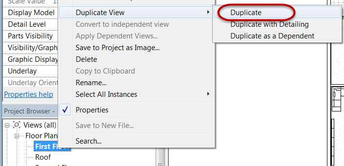
Duplicate the First Floor plan view.
a. In Project Browser, select First Floor plan view name.
b. Right click the named view and select Duplicate View \ Duplicate.
c. Rename the copied version of the view in Project Browser by right clicking the name and select Rename.
d. Rename view to: Level 1 – Structural.
e. Click OK to continue.
-
Turn off the visibility of specific element categories.
a. On the View tab, Graphics panel, click Visibility / Graphics tool.
b. Unmark the following categories on the Model Categories tab.
Furniture

Furniture systems

Specialty equipment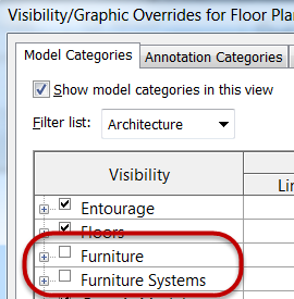
*Note: Specialty equipment category not shown.*c. Click OK.
-
Override graphic properties of structural columns to be a heavier lineweight and change the color to red.
a. Open Visibility / Graphics Overrides dialog box, type shortcut: VG.
b. Scroll down and expand the Structural Column category.
c. Override the Cut line property (Mark 1) for Stick Symbols sub-category and assign a lineweight of 8 (Mark 2) the color red (Mark 3).
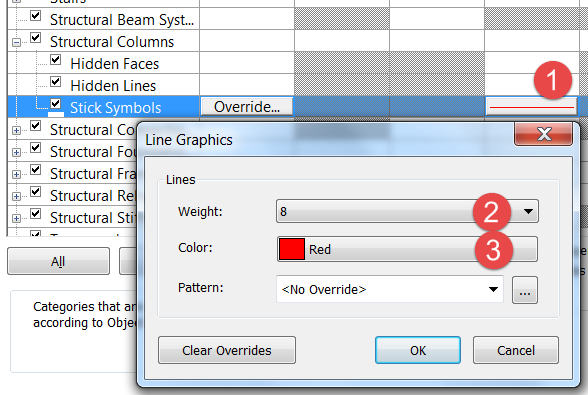
d. Click OK to continue.
e. Click OK to exit the Visibility / Graphics Overrides dialog box.
-
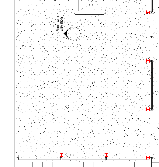
Finished override results below.
Create a Level 1 Furniture plan view
This plan view will focus on emphasizing furniture elements in a specific color.
-
Open the First Floor plan view.
-
Duplicate the First Floor plan view.
a. In Project Browser, select First Floor plan view name.
b. Right click the named view and select Duplicate View \ Duplicate.
c. Rename the copied version of the view in Project Browser by right clicking the name and select Rename.
d. Rename view to: Level 1 – Furniture.
e. Click OK to continue.
-
Override graphic properties of non-furniture categories to halftone effect.
a. Open Visibility / Graphics Overrides dialog box, type shortcut: VG.
b. On the Model Categories tab, Scroll down and place the following categories in a selection set:
Furniture

Furniture systems

Specialty Equipment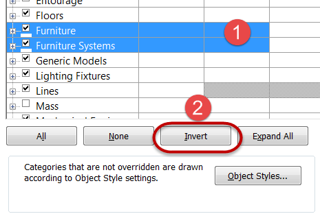
*Note: Use CTRL + Left click with mouse to build a selection
set.*
c. Click Invert to invert the selected model categories.
d. Mark the Halftone property (Mark 1) for any of the selected > categories and it will apply that property to all selected > categories.
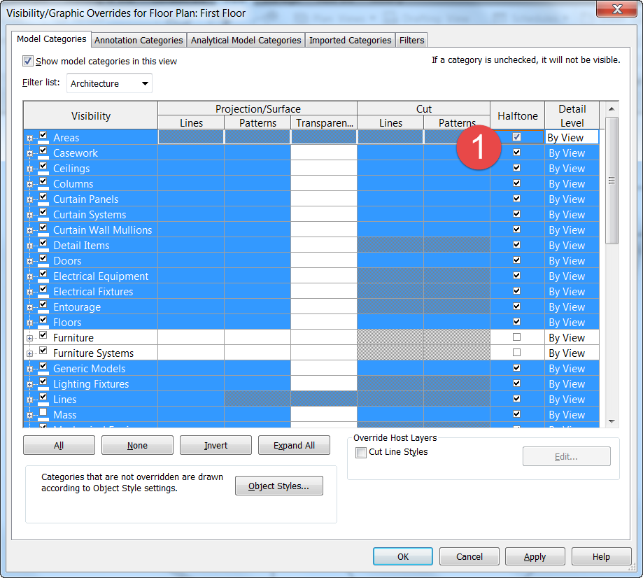
e. Click OK to continue.
-
Progress override results below.
-
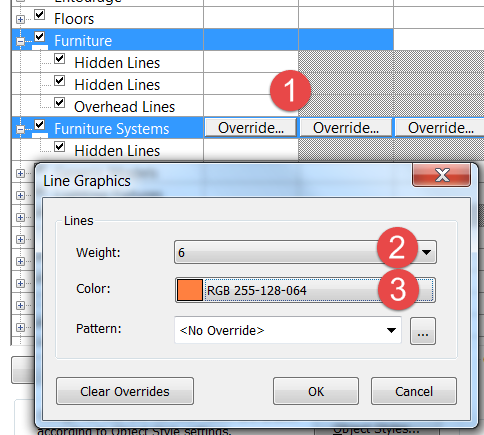
Override graphic properties of furniture categories to be of a different color.
a. Open Visibility / Graphics Overrides dialog box, type shortcut: VG.
b. Scroll down and select both furniture categories.
c. Override the Projection / Surface line property (Mark 1) for Lines and assign it a lineweight of 6 (Mark 2) and the color orange (Mark 3).
d. Click OK to continue.
e. Click OK to exit the Visibility / Graphics Overrides dialog box.
-
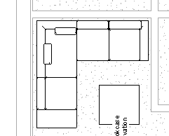
Finished override results below.
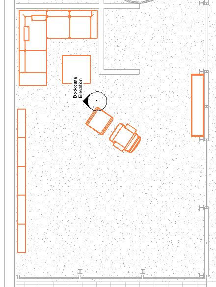
Note: Partial floor plan shown.
Create a Level 1 Residence only plan view
This plan view will focus on just the Residence area of the house.
-
Open the First Floor plan view.
-
Duplicate the First Floor plan view.
-
Rename copied view to:
First Floor – Residence.
-
Turn on crop window for the view and resize it.
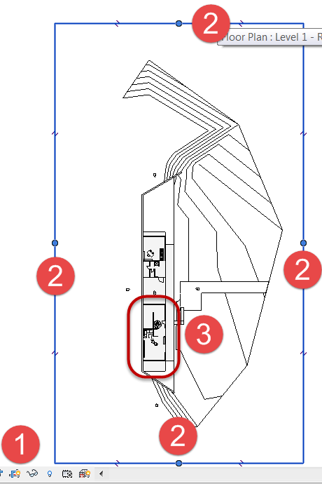
a. Click Show Crop Region tool (Mark 1) in the View Control toolbar.

b. Select the crop region in the canvas window and use the blue drag handles (Mark 2) to resize the window to appear just around the Residence area indicate by Mark 3.
-
Hide the Crop Region Window when done.

-
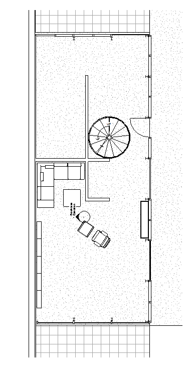
Finished crop region resizing results below.
Create a Level 2 Residence only plan view
This plan view will focus on just the Residence area of the house.
-
Repeat the steps shown for creating the previous plan view for the Second Floor plan view.
-
Rename Second Floor view to:
Level 2 – Residence.
-
Crop the view region to just the Residence plan only similar to Level 1- Residence plan view.
-
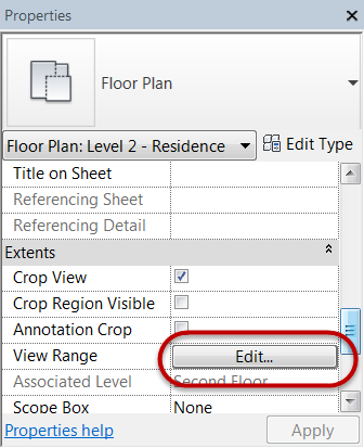
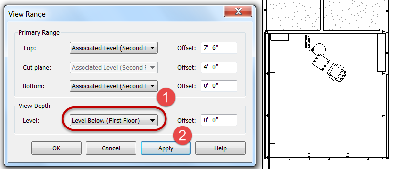
Change the View Range parameters to see the first floor below.
a. In Properties palette, scroll down to Extents category and click Edit button for View Range.
-
In View Range dialog box, set View Depth to: Level Below. (Mark 1) and click Apply (Mark 2) to see the results in the canvas window.
-
Click OK to dismiss dialog box.
-
Save the Revit file as: Module06Ex01.rvt
This concludes Exercise 1.